
Specifications #
- Input Voltage: 4V – 40V (needs to be a minimum 1.5V higher than the output)
- Output Voltage: 1.3V – 35V (Continuous Adjustable)
- Maximum Output Current: 3A (Maximum current is dependent on input and output voltages, ambient temperature and cooling)
- Voltmeter Resolution: ±0.1V
- Voltmeter Digital Display Range: 0v-45v
- Voltmeter Input Voltage Range: Dc 4v-40v
- Size : 66 x 36mm x 14mm
Interface #
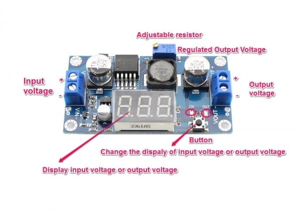
Usage #
LED LIGHTS
- When the green led light is lit up on the board, the display will show the output voltage.
- When the red led light is lit up on the board, the display will show the input voltage.
CALIBRATION
- Power up the module with a stable and accurate power supply, such as a 5V power supply, and long pressing (press time > 4S) the button makes the module enter the calibration model; after releasing the button, the related LED would light up to indicate which voltage is now calibrating, and the numeric display blinks the correction value.(Default: 0.0V)
- Short press the button to change the correction value(-0.5V ~ 0.5V); for example, if your power supply is 5V, but the result of the voltage meter is 4.8, you need to set the correction value to +0.2V.
- Long press (press time ≈ 2S) to store the input voltage correction value; the module will enter the output voltage correction value calibration model automatically.
- Calibrate the output voltage in the same way above; The correction value will be stored in nonvolatile memory.


