
Pin Definition #
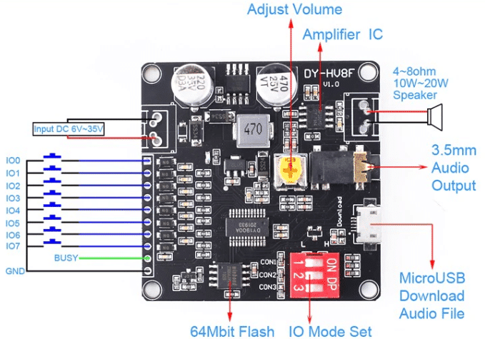
| POWER + | Voltage Positive Input |
| POWER – | Voltage Negative Input |
| TXD/IO0 | IO Trigger Mode Input IO0 – UART mode is TX |
| RXD/IO1 | IO Trigger Mode Input IO1 – UART mode is RX |
| IO2 | IO Trigger Mode Input IO2 |
| IO3 | IO Trigger Mode Input IO3 |
| IO4/ONE_LINE | IO Trigger Mode Input IO4 – ONE_Line mode Data Receiver Pin |
| IO5 | IO Trigger Mode Input IO5 |
| IO6 | IO Trigger Mode Input IO6 |
| IO7 | IO Trigger Mode Input IO7 |
| BUSY | Output Low-Level Signal (0V) When Playing and Output High (3.3V) after Playing |
| GND | Ground |
Configuration #
[table id=131 /]
NOTE:
1: “Key combination play”: Return to the original high level after the corresponding level from I/O0 – I/O7 output, similar to the key triggered once. Similar instantaneous switch.
2: “Level combination play”: The trigger signal remains similar to a self-locking switch.
2: The difference between “I/O integrated/independent mode 0” and “I/O integrated/independent mode 1” – Mode 0 will continue playing the current song to the end after the release level, and Mode 1 will stop playing immediately after the release level.
I/O Integrated Mode 0 (key combination playing) #
NOTE: the song must be named for 5bit.
| IO7 | IO6 | IO5 | IO4 | IO3 | IO2 | IO1 | IO0 | Song |
| 1 | 1 | 1 | 1 | 1 | 1 | 1 | 0 | 00001.mp3 |
| 1 | 1 | 1 | 1 | 1 | 1 | 0 | 1 | 00002.mp3 |
| 1 | 1 | 1 | 1 | 1 | 1 | 0 | 0 | 00003.mp3 |
| 1 | 1 | 1 | 1 | 1 | 0 | 1 | 1 | 00004.mp3 |
| 1 | 1 | 1 | 1 | 1 | 0 | 1 | 0 | 00005.mp3 |
| 1 | 1 | 1 | 1 | 1 | 0 | 0 | 1 | 00006.mp3 |
| 1 | 1 | 1 | 1 | 1 | 0 | 0 | 0 | 00007.mp3 |
| —- | —- | —- | —- | —- | —- | —- | —- | —- |
| 0 | 0 | 0 | 0 | 0 | 0 | 0 | 0 | 00255.mp3 |
It will stop playing the current song to the end after I/O0-7 releases the input signal (return to high) at ‘I/O Integrated Mode 0’. It will play a new song when receiving a new input signal while playing a song and stop after the end of the song. It will repeatedly play if the signal is kept. Busy pin output HIGH signal during playing. Music control following.
Dimensions #
50mm x 50mm


